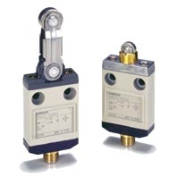
Description
Ratings
| Rated voltage | Non-inductive load (A) | Inductive load (A) | ||||||
|---|---|---|---|---|---|---|---|---|
| Resistive load | Lamp load | Inductive load | Motor load | |||||
| NC | NO | NC | NO | NC | NO | NC | NO | |
| 125 VAC | 1 | 1 | 1 | 0.7 | 1 | 1 | 1 | 1 |
| 30 VDC | 1 | 1 | 1 | 1 | 1 | 1 | 1 | 1 |
Note: 1. The above current ratings are for steady-state current.
2. Inductive loads have a power factor of 0.4 min. (AC) and a time constant of 7 ms max. (DC).
3. Lamp loads have an inrush current of 10 times the steady-state current.
4. Motor loads have an inrush current of 6 times the steady-state current.
2. Inductive loads have a power factor of 0.4 min. (AC) and a time constant of 7 ms max. (DC).
3. Lamp loads have an inrush current of 10 times the steady-state current.
4. Motor loads have an inrush current of 6 times the steady-state current.
D4CC-3, D4CC-4, 1 A at 30 VDC
| Inrush current | NC | 5 A max. |
|---|---|---|
| NO | 2.5 A max. |
Characteristics
| Degree of protection | IP67 | |
|---|---|---|
| Durability *1 | Mechanical | 10,000,000 operations min. |
| Electrical | 200,000 operations min. (1 A at 125 VAC, resistive load) | |
| Operating speed | 0.1 mm/s to 0.5 m/s (in case of plunger) 1 mm/s to 1 m/s (in case of roller lever) |
|
| Operating frequency |
Mechanical | 120 operations/min |
| Electrical | 30 operations/min | |
| Rated frequency | 50/60 Hz | |
| Insulation resistance | 100 MΩ min. (at 500 VDC) | |
| Contact resistance (initial) | 100 mΩ max. | |
| Dielectric strength |
Between terminals of same polarity | 1,000 VAC, 50/60 Hz for 1 min |
| Between current-carrying metal parts and ground |
1,500 VAC, 50/60 Hz for 1 min | |
| Between each termi-nal and non- current-carrying metal part |
1,500 VAC, 50/60 Hz for 1 min | |
| Vibration resistance |
Malfunction | 10 to 55 Hz, 1.5-mm double amplitude *2 |
| Shock resistance |
Destruction | 1,000 m/s2 max. |
| Malfunction | 500 m/s2 max. *2 | |
| Ambient operating temperature | -10°C to +70°C (with no icing) | |
| Ambient operating humidity | 35% to 95%RH | |
| Weight | Approx. 120 g (in the case of D4CC-1002) | |
Note: The above figures are initial values.
*1. The values are calculated at an operating temperature of +5°C to +35°C, and an operating humidity of 40% to
70%RH. Contact your OMRON sales representative for more detailed information on other operating environments.
*2. Excluding plastic rod models.
*1. The values are calculated at an operating temperature of +5°C to +35°C, and an operating humidity of 40% to
70%RH. Contact your OMRON sales representative for more detailed information on other operating environments.
*2. Excluding plastic rod models.
Leakage Current for Switches with Indicators
The leakage current and resistance of Switches with indicators are as follows:
| Item Model | D4CC-2[][][] | D4CC-4[][][] |
|---|---|---|
| Voltage | 125 VAC | 30 VDC |
| Leakage current | 1.0 mA | 1.0 mA |
| Resistive value | 150 k Ω | 30 k Ω |


Reviews
There are no reviews yet.